
 English
  German
  Spanish
  Italian
  Russian
  Arabic
  Korean
  Japanese
  French
  Dutch
Dutch  Danish
  Norwegian
  Portuguese
  Turkish
  Czech
Czech  Lithuanian
  Polish
  Slovenian
 LSR Molding: What Actually Matters in Mold Design
Table of Contents
If you work with LSR molding, you already know this: the mold decides everything. Material, machine, and settings help—but if the mold design is off, nothing else saves the part.
I’ve seen molds that looked perfect on paper fail in the first trial. Usually not because of big mistakes, but small details—temperature drift, poor vent depth, or a cold runner that wasn’t really “cold.”
This guide walks through the key areas that tend to cause real problems in production.
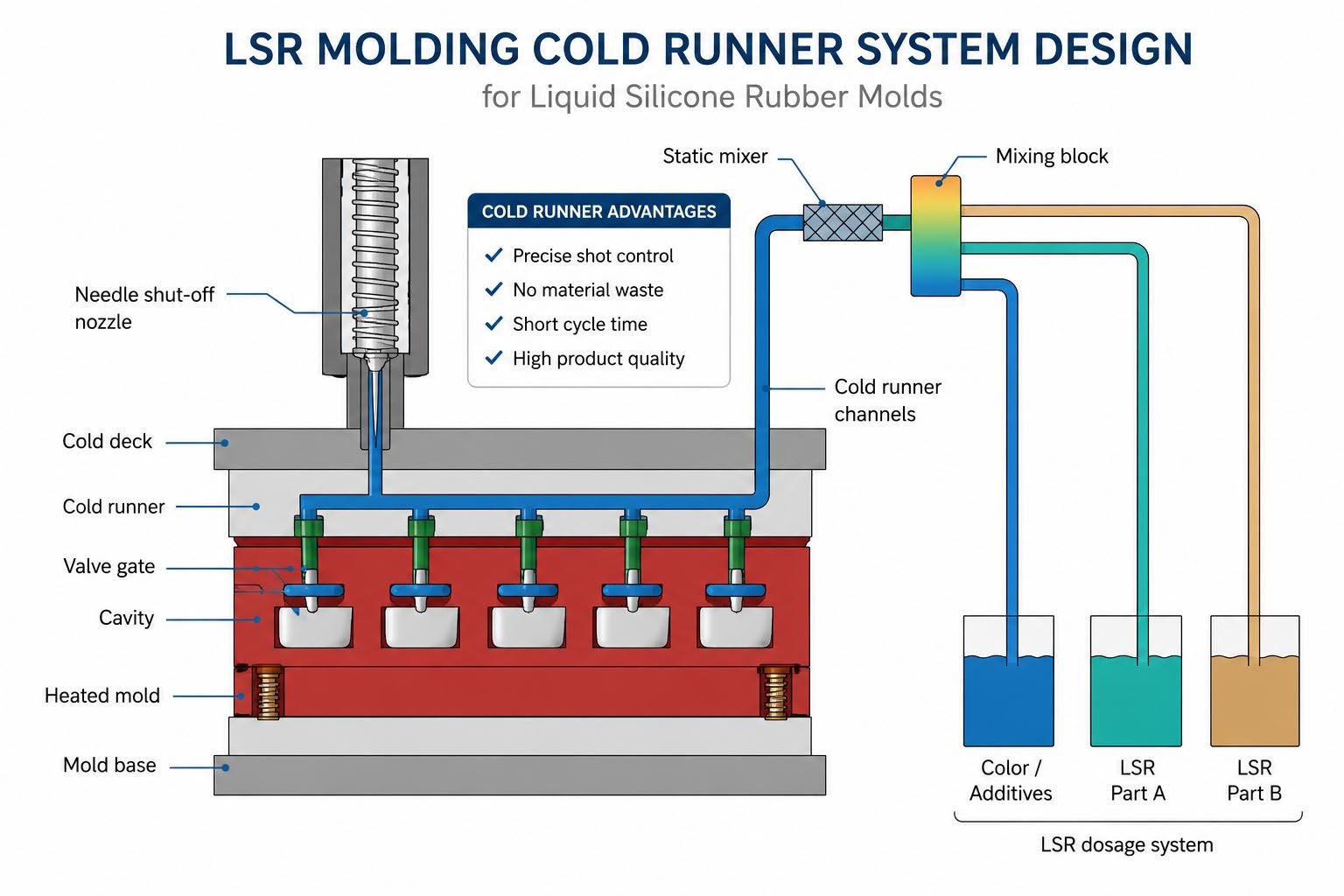
Cold Runner in LSR Molding: Temperature Separation First
Cold runner design is where many projects go wrong early.
LSR is not like thermoplastics. Once it gets warm, it starts to cure. So you need strict separation:
Three zones you must control
Cold side (around 20°C): keeps material stable before injection
Hot side (120–170°C typical): cures the part
Insulation layer: prevents heat transfer between the two
In one project for a baby bottle valve, the runner plate temperature crept above 30°C. The result? Partial curing inside the runner. We had blocked gates after just a few cycles.
The fix was simple in theory: add proper cooling channels and improve insulation. In practice, that meant reworking the entire plate.
What to watch
Cooling channels in the nozzle are not optional
Titanium insulation plates help reduce heat transfer
Valve gate control matters, especially for parts under 1 gram
Venting Design in LSR Molding: Microns Matter
LSR flows easily. That’s good for filling—but bad for venting.
If your vent is too deep, you get flash. Too shallow, you trap air.
Practical vent range
Depth: 0.004–0.005 mm works in most cases
Width: 1–3 mm
Location: last fill area (use flow analysis, not guesswork)
We once had a medical seal with random burn marks. The vents were “standard,” but not placed correctly. After running Moldflow, we found the real air trap was on the opposite side.
Adding a vent there solved the issue without touching the process.
When venting is not enough
For complex parts, vacuum helps a lot. Pulling down to about −0.09 MPa before injection can remove most trapped air.
Related Articles:
Shrinkage in LSR Molding: Not a Fixed Number
A common assumption: shrinkage is 2.5%. Just scale the mold.
That works—until it doesn’t.
LSR shrinks after demolding, not during packing like thermoplastics. So you don’t “fix” size with pressure.
What actually affects shrinkage
Flow direction (higher along flow)
Wall thickness (thin sections shrink more)
Mold temperature
Demold temperature
Post-curing
On a long, thin gasket, we saw over 3.5% shrinkage along flow, but only about 2% across it. If we had used a single value, the part would never meet tolerance.
Flash Control: It Starts with the Parting Line
Flash is not just a process issue. It’s mostly a mold issue.
LSR will find any gap.
Three levels of control
Design level:
Reduce inserts where possible
Plan flash tear lines early
Use mushroom or tapered ejector pins
Machining level:
Parting surfaces must be matched at micron level
Ejector clearances must stay tight
Process level:
Use staged clamping with vacuum if possible
I’ve seen shops increase clamp force to fix flash. It helps sometimes—but if your parting line isn’t tight, silicone will still leak through.
Temperature Control: Uniformity Beats High Heat
You don’t need the highest temperature. You need stable temperature.
Typical ranges
Standard LSR: 120–150°C
Fast cycles: 160–170°C
Avoid going above 180°C
The bigger problem is uneven heat.
One mold we reviewed had a 10°C difference across cavities. Some parts cured fine, others stayed soft. The root cause was poor heater placement and shared sensors.
Key points
Keep temperature variation within ±3°C
Place heaters evenly and close to the cavity
Avoid putting heaters too near the parting line
Mold Material and Demolding: Often Overlooked
Material choice matters more when you run high temperature cycles every day.
Typical selections
Standard LSR: hardened tool steel
High wear or filled LSR: coated or powder metallurgy steel
Optical parts: polished steel
For demolding, surface treatment helps a lot.
PTFE or nickel coatings reduce sticking. Combine that with a 0.5–1° draft angle, and most parts release cleanly.
Relying on release agents long term usually creates more problems than it solves.
FAQ: LSR Molding Design
What is the ideal vent depth for LSR molding?
Around 0.004–0.005 mm. Going above 0.02 mm will almost always cause flash.
Why is cold runner design critical in LSR?
Because LSR starts curing above about 30°C. Poor cooling leads to blockages and scrap.
How much does LSR shrink?
Typically 2% to 4%, but it varies by flow direction, thickness, and curing conditions.
How do you reduce flash in LSR parts?
Focus on parting line precision, minimize gaps, and control mold alignment before adjusting process settings.
Is vacuum necessary in LSR molding?
Not always, but for complex or thin parts, it greatly improves venting and reduces defects.
Contact US to Discuss Your Project Today
Successful LSR molding starts long before the first production run.
Cold runner performance, vent design, shrinkage compensation, flash prevention, temperature control, and material selection all work together. Weakness in one area often creates problems elsewhere.
When mold design addresses these factors from the beginning, production becomes more predictable, scrap rates fall, and dimensional consistency improves over the life of the tool.